

Description
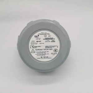
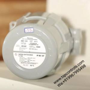
Booster Relay BR400 | Masoneilan
- Product name : Masoneilan-Booster-Relay-
BR400 - Condition: Brand new
- Brand : GE ( Masoneilan)
- Origin: US
Product Description:
Booster Relay BR400 | Masoneilan are high capacity volume boosters for applications that require fast stroking speeds using pneumatic actuators. Stable operation over a wide range of actuator sizes can be obtained by adjusting the bypass valve on the booster to modify the dynamic response. The BR400 and BR200 are equally suitable for use on diaphragm or piston actuators.
Features and Benefits
Flow characteristics suitable for control valves
Provides short stroking times with consistently stable operation
Built-in bypass valve with locking screw to adjust sensitivity and dynamic response
Filters on both the supply and signal ports
Corrosion resistant finish and stainless assembly hardware to permit use in corrosive atmosphere
Specifications of Booster Relay BR400:
Maximum Cv (supply) 1.2 (BR200) and 2.6 (BR400)
Maximum Cv (exhaust) 1.2 (BR200) and 2.4 (BR400)
Max Signal Pressure 150 psi (10.3 bar)
Operating Temperature Limits
-30ºC to +83ºC (-22ºF to +181ºF)
Low Temperature: -55ºC to +60ºC (-67ºF to +140ºF)
High Temperature: 0ºC to +100ºC (32ºF to +212ºF)
Input / Output Ratio 1:1
Supply and Output Connections 1/4” NPT or Rc (BR200) and 1/2″ NPT or Rc (BR400)
Signal Connection 1/4″ NPT or Rc
Approximate Weight 0.7 kg (1.5 lbs) for BR200 and 1.4 kg (3 lbs) for BR400
Principle of Operation of Booster Relay BR400:
The input signal pressure is applied to the upper diaphragm to produce a force that is opposed in a 1:1 ratio by the output pressure acting on the lower diaphragm through the seal plate orifice. An increase in the input signal pressure will depress the top diaphragm and open the pilot valve, allowing supply pressure to the output until the output pressure action on the lower diaphragm re-balances the forces. conversely, a decrease in the input signal pressure allows the exhaust valve to open until the output pressure falls to the same value as the input signal pressure…more
Pneumatic Connections
The pneumatic connection in Masoneilan Booster Relay BR400/BR200 consists of supply and output connections of ½” NPT and the signal connection is ¼” NPT. The supply and output tubing should be a minimum of ½. Blow out all piping prior to connecting to booster. Use of a soft setting anaerobic hydraulic seal,such as Loctite Hydraulic Seal 542 is recommended on the male threads of all connections
Pneumatic Supply
The BR400 and BR200 Booster Relays require a source of clean, dry, oil-free, instrument grade air to ANSI/ ASA-57.3 1975 (R1981) or ISA-S7.3-1075 (R1981)
Maximum Supply Pressure 150 psi (10.3 bar)
Dew Point At least 18°F (10°C) below minimum anticipated ambient temperature.
Particulate Matter Filtered to below 5 microns.
Oil Content: Less than 1 ppm w/w or v/v.
Contaminants Free of all corrosive contaminants and hazardous gasses, flammable or toxic.
Material of Construction
1 Body = Aluminium Alloy Die Casting
2 Case = Aluminium Alloy Die Casting
3 Upper Diaphragm = Chloroprene / Polyester
4 Lower Diaphragm = Chloroprene / Polyester
5 Lower Diaphragm Plate = Aluminium Alloy Plate
6 Exhaust Seat = Copper Alloy
7 Seal Plate = Austenitic Stainless Steel
8 Exhaust Seal Guide = Copper Alloy
9 Seal Plate Gasket = Inorganic Fiber/Oil Resistant Synthetic Rubber
10 Plug Cap = Copper Alloy
11 Coil Spring = Austenitic Stainless Steel
12 Plug = Austenitic Stainless Steel
13 Bypass Valve Plug = Austenitic Stainless Steel
14 Piston= Glass Fiber Reinforced Thermoplastic Polyester
15 Supply Filter = Austenitic Stainless Steel
16 Signal Filter = Austenitic Stainless Steel
17 Bleed Ring = Aluminium Alloy Die Casting
Installation
The booster relay should be close coupled to the actuator. Use of a short ½” pipe nipple between the relay output and the actuator provides both the pneumatic connection and mounting means. The preferred orientation is with the exhaust openings pointing down; however horizontal mounting is acceptable.
Operation
Prior to applying supply pressure to the relay, open the bypass needle valve approximately one turn. After applying pressure, note response of actuator to open and close commands from the positioner. If Excessive overshoot or hunting is seen, open needle valve until stable operation is obtained. If valve is sluggish, close needle valve until unstable operation occurs, then back off until stable operation is obtained. Turning valve clockwise (closing) speeds response but can lead to instability. Turning valve counterclockwise aids stability but will slow down the actuator’s response. Proper setting provides stable operation and acceptable response time.
Maintenance
The BR400 Booster Relay does not require any routine maintenance. If a contaminated air supply has been used, then there may be need to clean the filters or disassemble the relay to clean the supply and exhaust seats and valves.
Troubleshooting
If the output pressure does not respond to changes in the input pressure, check that supply pressure is at proper value and that signal and supply filters are not plugged with foreign matter. Check also that supply and exhaust valve seats are clean. If output pressure is not stable or is slow to respond, check setting of bypass needle valve. See bypass valve setting procedure under “Operation”.
For complete datasheet : TSP Controls – Masoneilan Booster relay BR400 Datasheet


Reviews
There are no reviews yet.